Analog Signal
In the previous lesson, we worked with digital pins. Now we’ll work with analog signals.
Digital pin:
Arduino digital pins are used to send digital signals to other devices such as LEDs, sensors, or actuators. They can be either in a high (1) or low (0) state, representing binary on/off signals. These pins can be used for digital inputs or outputs, and can also perform simple digital operations such as reading button presses, controlling LEDs
An analog signal is a continuously changing electrical signal. Think of turning up and down the volume on a radio; this change represents an analog signal. Analog signals can vary continuously, often carrying information related to the real world, such as music sounds or someone speaking.

What is Analog Pins ?
Arduino analog pins are input pins that can read analog signals and convert them into digital signals that can be read by the microcontroller. They are used to read analog values from sensors or other devices that provide continuous
Arduino boards have a limited number of analog pins, which can vary depending on the model. On the most popular Arduino board, the Arduino UNO, there are 6 analog pins (A0 to A5). These pins are labeled with the letter “A” followed by a number, and they can be used to read analog signals such as those from sensors or potentiometers. These analog signals can then be processed and used to control devices or perform other functions in your project.
“Analog values range between 0 and 1023. If a 5-volt voltage is applied to the analog pin, its digital equivalent will be 1023 (this value is related to the structure of the Arduino Uno). When a value between 0 and 5V is applied, the Arduino processor proportionally divides it to calculate its digital equivalent. For example, if a value of 3.25V is applied, its digital equivalent is approximately 665.”
When using analog signals in our programming processes, we must pay attention to this ratio and proportion.
Analog Project-1: Moving Leds
We will use a potentiometer with an adjustable resistor to obtain an analog value. The potentiometer adjusts the 5V voltage to different voltage values. We will make a moving light using the potentiometer. In our project, we will turn on the lights in sequence using different voltage ranges obtained from the potentiometer.
I previously mentioned that the analog value from the potentiometer is converted into a digital value between 0-1023. Now, we will divide the values received from the potentiometer into certain ranges and sequentially feed them to the pins that control the LEDs. As we turn the potentiometer, the corresponding pin in the relevant range will become active.
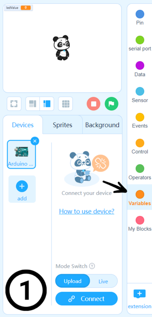
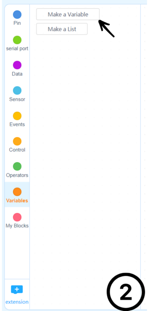
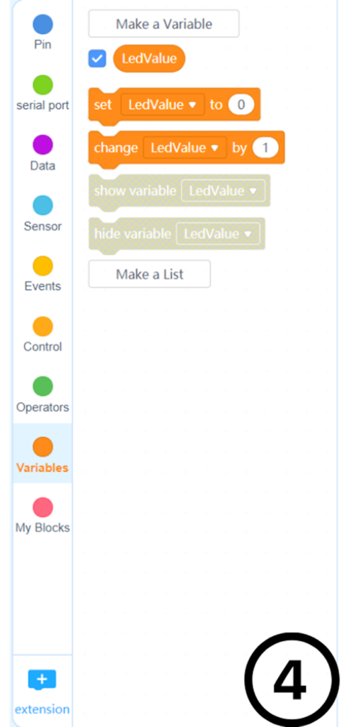
Here we will use a new feature called creating variables. Let me briefly explain what a variable is. Variables are areas where a value is stored in programming. We will create a LedValue variable in the project and store the analog value inside it.
You can create a new variable by following the steps below.


Before we start coding, let’s draw our circuit. As seen in the diagram below, I will use digital pins (2), (3), (4), (5), (6).

Codding:
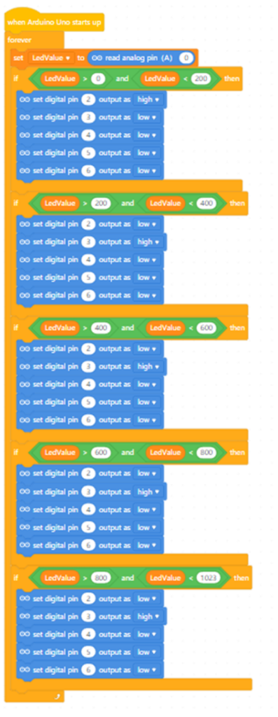
Now we can start coding. First, we need to define the analog pin we will use. In this project, we will use the A0 pin. Arduino will convert the analog information from this pin into a digital value (0-1023). By dividing the converted digital values into specific ranges, we will decide which digital pin to activate. To ensure equal distribution, I divided it into 200-unit parts (I will use 5 LEDs).

After selecting the required analog pin, I will choose which digital pin will be activated by the digital value between 0 and 200. To keep it sequential, I will activate the Digital (2) pin to which my first LED is connected and deactivate the other digital pins.

Now, I will divide it into 200-unit parts sequentially and activate the other digital pins in order.
Pin 3

Pin 4

Pin 5

Pin 6
I am selecting the last pin between 800 and 1024 because if I choose between 800 and 1000, Arduino will not output anything for the range 1000 to 1024 since no selection has been made for that range.

Here is the complete program.


